The Fingers Crossed Stage: PRINTING & MEASURING
- Obiefuna Obidike
- Apr 18, 2022
- 4 min read


Finally! Here we are!
The fingers crossed the stage. In my opinion, I believe every manufacturer no matter their pre-design and design phase always gets anxiety during the actual manufacturing stage where all the time spent in planning and designing will be put to test.
For this project, I mapped out phases of the printing stage that I will be expatiating on:
PRINTING SETUP
After loading the printer with the material and right print core, I saved the sliced model from Cura on a pen-drive as a "UFP" that can be read by the Ultimaker printers, in my case the Ultimaker s5 printer which has an LCD touch display that I made use of in giving the printer instructions to start printing.

WAIT FOR THE FIRST LAYER
With the instructions I gave to the printer, the printer heated its printing bed and started moving its printing cores in the X and Y direction to calibrate itself. "For the Ultimaker and most 3D printers, the motion is that the print cores move in the X and Y direction while the print bed moves in the Z direction that's why & how the printer prints layer by layer".
After the preliminary stage of the printing, I waited to see the base layer of the print formed. in this printing job, the print formed a blob (which wouldn't be used during mass printing ), and a skirt. that gave me the confidence to go ahead with other activities while the printer does its work.
PRINT RESULT
With the printer running for 7 hours 11 minutes due to printing 5 print models with their individual print settings and general print setting, I waited for the print bed to cool off so that I could take off the prints. I also added labels to some of the prints to avoid wastage of material and cover up the fault in the design pointed out here.

It is worth pointing out from the picture below, that the ease of removal of the prints from the bed was easy for prints 1, 3 and 4 which I had initially enabled their support interface than that of print 2 which didn't receive the same during the individual print setup.

POST PRINTING
At this stage, I had my prints which looked pretty fine but with some off shots from the design. Although these off-shoots look like they can be neglected, they can be an issue during production if they are neglected. They can cause delay, malfunction and even downtime of machines and as we know, they say "Time is Money".



Making use of a Sandpaper, I was able to chip off these kinds of off-shoots to restore the prints to an ideal design.
However, I am left to wonder if it's possible for the sanding process to be incorporated with the 3d printing process so that the output of printing can just be the sanded print. Hmm! probably something I would look into.


MEASURING
With post-printing out of the way, I went on to compare my print with a sample of the phone case part Phone-R-Us that had a disruption of supply (click here to help refresh your memory).

Making use of a vernier caliper in measuring my print and the sample 5 times each I noticed my measurement varied with each measure. I really did my best to be precise with each measure but I guess my 'young ageing' hands and possibly eyes had the final say haha!

Measuring the Inner depth (h), Inner length (L), and Inner breadth (B) five times and taking the average of all three measurements, I got the reading below. The varying measurement which seems very easy at first shows that it is not all that easy and it also brings to the limelight the nature of the human error in measurement.


I went further, to compare both print and sample by 3D scanning using the Hexagon Romer absolute arm 3D scanner. I must say that I was impressed by its features, it had a solid stand and its scanner was mounted on a fixture that I would say mimics the human shoulder movement. I was informed that it was priced at about £80,000 which screamed: "Handle with extreme care all over it".

Having a black sample from Phone-R-Us, I had to prep it for scanning by spraying white vanishing spray on it so that the scanner which scans white surfaces better would be able to scan the sample.
I didn't know why they call it vanishing spray until it had started vanishing off the sample some few minutes after I had finished scanning. Imagine convincing someone that you saw a white object only to come back a few minutes later to see that the object isn't white but another colour.
ha ha! but seriously it wouldn't be a funny joke if your life depended on the object being white.

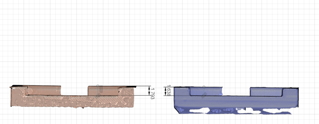
With that, I went on to scan both the sample and my print separately to get a 3D CAD model of both and export them as an STL file into Fusion 360 to enable me to take their dimensions and compare them.
However, the scan wasn't so complete leading to the variation I got in my measurement. However, I must say, it felt really good using the scanner, I got lost in it because I got the 007 (James Bond) feeling of holding the gun-like scanner while pointing it and the sample to be scanned.


Remember from in my previous post I mentioned I would be using the Datron CNC machine to do some measurements.
Well, I did use it but it had a shortfall; it has a thin straight face with a small height on which any part that is to be measured can be clamped. Because of this constraint, I could only measure the back of my part and could not turn it over to measure the internal part because my print had a beveled end towards the bottom where it was to be clamped.
I think this error points out that at the design stage, designing for measurement should be a consideration. However, the design is not of mine but of my client, Phone-R-Us so I can not really alter the design.
The Big Question again is, were all these measurements worth the time it cost to do them?


Comments